Monitor Rack: Difference between revisions
From YSTV Documentation Wiki
(New photo, more updates for HD) |
m (HDOK - The CRTs have migrated) |
||
| Line 1: | Line 1: | ||
{{ | {{HDOK}} | ||
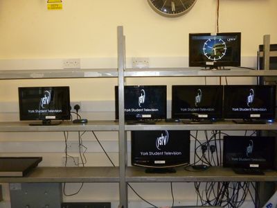
[[File:Monitor Rack.JPG|400px|right|thumb|The monitor rack as of 11/11/2013. The YSTV logo is showing on the commonly used monitors]] | [[File:Monitor Rack.JPG|400px|right|thumb|The monitor rack as of 11/11/2013. The YSTV logo is showing on the commonly used monitors]] | ||
This is where we place all the monitors to allow us to see what's happening at different parts of the vision path. | This is where we place all the monitors to allow us to see what's happening at different parts of the vision path. | ||
Revision as of 21:05, 3 January 2014
This is where we place all the monitors to allow us to see what's happening at different parts of the vision path.
Power
The monitor rack is fed power from circuits 1 and 2 in the control room. Circuit 1 powers the left side, while 2 does the right.
Signal
The signal cables are ended with BNC connectors and numbered from 1 to 18. The numbering starts from the top left of the rack, and goes left to right, top to bottom with 18 being bottom right. The inputs for these are located in the patch bay.
This is converted to HDMI at each monitor by some cheap HD-SDI to HDMI converters.
Usage
The current usage is:
The Stream monitor is fed directly via HDMI from a capture card in the server rack.
