Vision Path: Difference between revisions
No edit summary |
No edit summary |
||
| Line 1: | Line 1: | ||
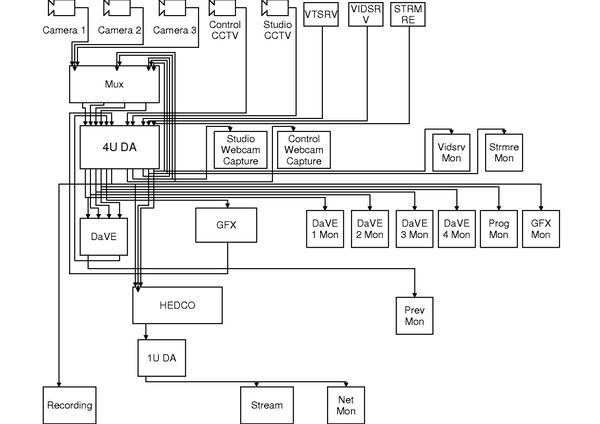
[[File:Analogue.jpg|thumb|600px|right|A (rough) diagram of the current vision path]] | |||
==General== | ==General== | ||
YSTV's cable jungle is 'maintained' regularly, usually before a show when something needs changing in a hurry. Currently, the path is incomplete, as we are waiting upon PCB manufacture for a new set of routers.The latest up to date written copy of the path can be found at <i>Docs>tech>visionpath</i>. Monitor rack connections vary rapidly according to requirements, and so are not here - sorry, but they will only add to the confusion! | YSTV's cable jungle is 'maintained' regularly, usually before a show when something needs changing in a hurry. Currently, the path is incomplete, as we are waiting upon PCB manufacture for a new set of routers.The latest up to date written copy of the path can be found at <i>Docs>tech>visionpath</i>. Monitor rack connections vary rapidly according to requirements, and so are not here - sorry, but they will only add to the confusion! | ||
==Colour scheme== | ==Colour scheme== | ||
In order to attempt to make the path more readable, the vision path is slowly being recoloured, in the hope that someone can just look at it (with a key) and state "this must be a camera", or "this is network critical". This also has the unexpected side effect of the vision path now looking comparatively neat, almost a work of art. Anyway, the scheme has been divided into main regions: Servers, Network, Routing, Cameras, Monitor feeds. Of each colour cable, try to cycle the boot colours on a per cable basis (not different per end!). This will make for quicker visual identification of cables (good before a show!). | In order to attempt to make the path more readable, the vision path is slowly being recoloured, in the hope that someone can just look at it (with a key) and state "this must be a camera", or "this is network critical". This also has the unexpected side effect of the vision path now looking comparatively neat, almost a work of art. Anyway, the scheme has been divided into main regions: Servers, Network, Routing, Cameras, Monitor feeds. Of each colour cable, try to cycle the boot colours on a per cable basis (not different per end!). This will make for quicker visual identification of cables (good before a show!). | ||
| Line 19: | Line 21: | ||
* Orange >> Computer Network data. | * Orange >> Computer Network data. | ||
** Easy to spot the odd one out now! | ** Easy to spot the odd one out now! | ||
[[Category:Technical]] | [[Category:Technical]] | ||
Revision as of 11:47, 5 June 2013
General
YSTV's cable jungle is 'maintained' regularly, usually before a show when something needs changing in a hurry. Currently, the path is incomplete, as we are waiting upon PCB manufacture for a new set of routers.The latest up to date written copy of the path can be found at Docs>tech>visionpath. Monitor rack connections vary rapidly according to requirements, and so are not here - sorry, but they will only add to the confusion!
Colour scheme
In order to attempt to make the path more readable, the vision path is slowly being recoloured, in the hope that someone can just look at it (with a key) and state "this must be a camera", or "this is network critical". This also has the unexpected side effect of the vision path now looking comparatively neat, almost a work of art. Anyway, the scheme has been divided into main regions: Servers, Network, Routing, Cameras, Monitor feeds. Of each colour cable, try to cycle the boot colours on a per cable basis (not different per end!). This will make for quicker visual identification of cables (good before a show!).
Colour Scheme Allocations:
- Red >> Network side cabling.
- Read means don't touch it unless you have to. Anything red is either critical control for the NetMux, or has come from the netmux, but is not going back into the main routing spaghetti.
- Blue >> Server Outputs.
- Vidserv, clock, inform, VTServ.
- Green >> Other inputs.
- This will be cameras.
- White >> Feed to monitors.
- Isn't it annoying when you can't spot where that monitor feed is coming from?
- Black >> Routing Mush.
- It's going to get fiddled with, and is the majority of the path so it might as well be the most common colour.
- Purple >> RS-XX2 data.
- It's different, and we have 300m spare!
- Orange >> Computer Network data.
- Easy to spot the odd one out now!
