LED Matrix
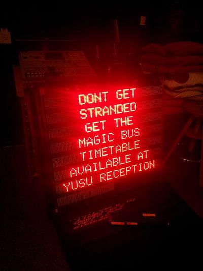
The LED boards came from a display board that sat outside Your Shop. In their past life they conveyed useful information about the magic bus, how to get NUS cards and the courtyard opening times. After some dismantling, starting at datasheets and tracing out; a vague schematic for the boards has been created.
The Basics:
The boards are relatively simple, they consist of two shift registers, an 8-bit buffer and three 16-bit serial LED drivers. The power supply to the boards should be 5V and around 2A.
Each board has 4 inputs (the names are not official), there is also a chain output on each board such that two (maybe more) can be connected in a line. The only change for this is the amount of data you clock in on each row scan.
| Pin | Function |
|---|---|
| CTRL_DATA | Control Data, used to transmit row data and enable the LED drivers. |
| COL_DATA | Data driven straight into LED drivers, 48 bits long. |
| CLK | Master clock for both COL and CTRL data. |
| STCP | Connected to STCP on first shift register, and also output enable. |
Driving the Board:
Clocking data into the LED drivers is trivial, setting the row is more difficult. IC2's outputs are connected (via FETs/transistors) to each row line. When the corresponding bit is 0, that row is enabled.
Example (Arduino) code (By Thomas Cheyney) for driving the boards is available from the MiscSoftware repo on YSTV's git server. At the time of writing there are timing issues to resolve and noticeable flicker.
