Tally (Roxanne)
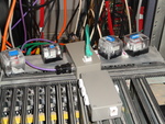
The tally system, also known by its codename Roxanne, is formed of a series of blocks mounted upon the camera hot-shoe mounts, which should illuminate when that camera is live using some data fed out by the vision mixer.
Tally Bricks
Each brick is a block of transparent resin. At the bottom is a hot-shoe mount, which should bolt on to the top of a camera. Encased inside is an RJ-45 jack, an LED bar and a rearwards facing LED, along with an 8-way switch mounted on top. 7 of the lines in the Cat-5 cable plugged into the rear can be driven by the control unit, and if that line is selected by the switch, the LEDs will illuminate. The remaining line in the Cat-5 cable acts as a ground return.
Splitter (Menorah)
The splitter, or Menorah as it's affectionately known, contains 5 RJ-45 jacks. Each of the 8 connectors on each jack is wired to the same connector on all the other jacks, causing it to look a little like a Menorah before being installed in the box. Despite looking like it would work for computer networking as well, it won't as all the connections are wrong, however it is designed to be placed at the point the umbilicals meet to connect to the wall, splitting the single line from the control room into one for each brick.
Control Unit
The control unit contains a connector to go to the vision mixer, an RJ-45 jack to connect to the rest of the system, a 4-pin XLR power connector and a female DB-9 connector for serial communications.
Connecting it up
The power connector is fairly obvious, anything doing more than about 7V should suffice, the 12V ones (cameras inc. Skycam) will do perfectly and it has an internal regulator. Maximum is around 24V - DO NOT use Howard's power supply. The RJ-45 connector goes to a length of Cat-5 cable running to the splitter in the studio, and the male DB-9 connector (like a monitor connector) goes to the GPI port on Magic DaVE. This has a slightly special cable, it's shown in the picture, but is a purple cable with a block plug on one end and a yellow on the other, should be easy to spot. Finally the female DB-9 connector can be run to a PC for serial communication. This means even when vision mixer input channels are reassigned and moved around on account of have 5 or more sources, the correct brick lights up when a camera is mixed to.
How it works
Inside the box are a trio of small stripboards. One of these is a simple 5V linear regulator delivering power to the system, this one has a big black heatsink attached to keep it cool. Another contains 4 small transistors, which are switched by the microcontroller to drive each of the four available tally lines. Each one corresponds to one of channels 1-4, with 5-7 currently unused (there is no channel 8, as that line is used as a ground return). The largest board contains a microcontroller running a simple program to detect changes on the vision mixer inputs, and light the appropriate bricks by turning on the line drivers. This board also contains a level shifter for the serial connection to remap what each channel does.
The magic remapping trick
At power-on, the system should default to each vision mixer input channel, 1-4 mapping to tally channels 1-4. A computer can connect using a serial link at 9600 baud to the control unit. Using YVP Protocol the computer can remap which vision mixer input each tally output follows. Ideally, this should be handled by the software controlling the mux that feeds the vision mixer, so that when a command is sent to the mux to assign a camera to a vision mixer channel, the corresponding command also goes to the tally system. At the time of writing, the only known example of this is the OB Director Control software used for Woodstock 2012, which might be in the Software drive, and is definitely in the YSTV Git repository. The software running on the control unit microcontroller is also with this OB Director software.
