Patch Panels: Difference between revisions
mNo edit summary |
|||
| (14 intermediate revisions by 3 users not shown) | |||
| Line 1: | Line 1: | ||
{{HDOK}} | |||
[[File:YSTV 2019 Patch Bay.jpg|300px|thumb|right|YSTV 2019 Patch Bay]] | |||
There are a number of boxes around the station, all feeding into the main patch bay behind the computing / vision racks. These contain a number of different connections for routing different signals to different areas of the station. | |||
== Patch Bay == | |||
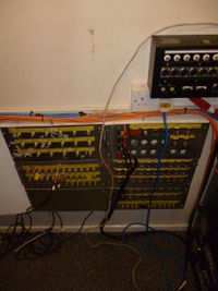
This is where all the patch boxes and a few cables feed to. This is due to the majority of patches needing to get to the vision or computing rack. All the connectors are grouped according to their type. The patches are then arranged in vertical stacks of pairs, due to the original 90's install determining available cable lengths. 95% of wiring is original to the 90's install when YSTV moved in. | |||
A few cables run separate from the patch boxes, including the monitor racks BNC/HDMI, overhead speakers, cat5 patch from ceiling in the tech room, and a blue cat5 line running via the truss to the lighting desk in the studio for DMX control. | |||
The types of patches available are: | |||
* BNC: SDI (1080i50). It's not really rated for digital, but is of good enough quality to work over the relatively short distances of the station. | |||
* XLR: M / F for mic / speaker / comms / DMX feeds. | |||
* RJ45: Now used as simple Cat5 patches (not 5e, just 5, but gigabit is fine), originally DB9 connectors to each patch box. | |||
* HDMI: Goes to the monitor rack. | |||
* Speakon: Wired as 4 pole, 2 poles were used for left, 2 poles for right of the control room and Studio speakers, to save rack space. | |||
== Patch Boxes == | |||
There are six main patch boxes throughout the station. Each box is assigned a number from 4 to 9. Numbers 1 to 3 are reserved for some unknown reason (possibly due to the lack of rubber cable number labels at the original install). Each connection is then given a number to give each patch a 2-digit number. The boxes feature XLR F, XLR M and BNC. The DB9 connectors are no longer connected and are routed to separate black RJ45 socket boxes instead. | |||
=== Box 4 === | |||
[[File:Patch box 4.jpg|thumb|right|150px|Patch box 4 (edit desk)]] | |||
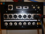
This box is located by the edit desk. It is different from all the other boxes in its connections. | |||
It contains 8 BNC, 4 XLR male, 4 XLR female, 1 XLR-5 female, 1 serial, 1 VGA, and 2 5-pin din serial connectors. The non-BNC/XLR connectors are not actually connected. | |||
= | === Box 5 === | ||
[[File:Patch_box_5.jpg|thumb|150px|left|Patch box 5 (Studio, next to the tech room.) Note the missing connectors]] | |||
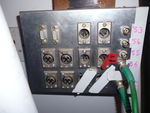
This box is located by the tech room in the studio. Apart from missing two BNC (51, 52) XLR male (54, 55) connectors and a slightly different panel it is identical to Boxes 6-9. | |||
The missing BNC and XLR connectors actually go through to the tech room and arrive on long cables hanging in one corner | |||
XLR 52 does arrive at this patch, but runs up to the clock for timecode. | |||
== | === Box 6 === | ||
[[File:Patch_box_6.jpg|thumb|150px|right|Patch box 6 (Monitor rack)]] | |||
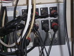
This Box is located by the monitor rack. The monitor connections do not pass through this box - it is for sending cables to the other side of the control room. Apart from its location it is identical to Boxes 7-9. | |||
| | |||
| | |||
| | |||
| | |||
=== Box 7-9 === | |||
These boxes are located around the studio. Each box contains 6 BNC, 6 XLR female, 4 XLR male and 2 serial connectors, of which most have been rewired to separate RJ45 boxes where accessible. | |||
== History == | |||
In September 2019, Matthew Stratford replaced the main patch bay in the control room. It's old age and custom handy work from the original 90's installation was taking its toll on reliability. The old panels were on hinges, with direct solder connections onto the thick cables. Opening up the panels to fix previous issues would likely lead to new breaks on reassembly. The DB9 connectors were replaced with Cat5 at either end during this. | |||
Matthew replaced the custom size panels with a standard 19" rack, with BNC pass-throughs for easier repair. Sadly, due to the workload of 3rd year Computer Science, Matthew never quite completed the task during his final year, before Covid19 struck. Matthew aims to return to complete the wood surround and the few incomplete connections as soon as possible, hopefully in 2021. | |||
[[File:Patch bay.JPG|thumb|left|200px|The patch bay (90's to 2019)]] | |||
[[Category:Audio]] | |||
[[Category:Vision Path]] | |||
[ | |||
[ | |||
Latest revision as of 09:34, 23 July 2021
There are a number of boxes around the station, all feeding into the main patch bay behind the computing / vision racks. These contain a number of different connections for routing different signals to different areas of the station.
Patch Bay
This is where all the patch boxes and a few cables feed to. This is due to the majority of patches needing to get to the vision or computing rack. All the connectors are grouped according to their type. The patches are then arranged in vertical stacks of pairs, due to the original 90's install determining available cable lengths. 95% of wiring is original to the 90's install when YSTV moved in.
A few cables run separate from the patch boxes, including the monitor racks BNC/HDMI, overhead speakers, cat5 patch from ceiling in the tech room, and a blue cat5 line running via the truss to the lighting desk in the studio for DMX control.
The types of patches available are:
- BNC: SDI (1080i50). It's not really rated for digital, but is of good enough quality to work over the relatively short distances of the station.
- XLR: M / F for mic / speaker / comms / DMX feeds.
- RJ45: Now used as simple Cat5 patches (not 5e, just 5, but gigabit is fine), originally DB9 connectors to each patch box.
- HDMI: Goes to the monitor rack.
- Speakon: Wired as 4 pole, 2 poles were used for left, 2 poles for right of the control room and Studio speakers, to save rack space.
Patch Boxes
There are six main patch boxes throughout the station. Each box is assigned a number from 4 to 9. Numbers 1 to 3 are reserved for some unknown reason (possibly due to the lack of rubber cable number labels at the original install). Each connection is then given a number to give each patch a 2-digit number. The boxes feature XLR F, XLR M and BNC. The DB9 connectors are no longer connected and are routed to separate black RJ45 socket boxes instead.
Box 4
This box is located by the edit desk. It is different from all the other boxes in its connections. It contains 8 BNC, 4 XLR male, 4 XLR female, 1 XLR-5 female, 1 serial, 1 VGA, and 2 5-pin din serial connectors. The non-BNC/XLR connectors are not actually connected.
Box 5
This box is located by the tech room in the studio. Apart from missing two BNC (51, 52) XLR male (54, 55) connectors and a slightly different panel it is identical to Boxes 6-9. The missing BNC and XLR connectors actually go through to the tech room and arrive on long cables hanging in one corner XLR 52 does arrive at this patch, but runs up to the clock for timecode.
Box 6
This Box is located by the monitor rack. The monitor connections do not pass through this box - it is for sending cables to the other side of the control room. Apart from its location it is identical to Boxes 7-9.
Box 7-9
These boxes are located around the studio. Each box contains 6 BNC, 6 XLR female, 4 XLR male and 2 serial connectors, of which most have been rewired to separate RJ45 boxes where accessible.
History
In September 2019, Matthew Stratford replaced the main patch bay in the control room. It's old age and custom handy work from the original 90's installation was taking its toll on reliability. The old panels were on hinges, with direct solder connections onto the thick cables. Opening up the panels to fix previous issues would likely lead to new breaks on reassembly. The DB9 connectors were replaced with Cat5 at either end during this.
Matthew replaced the custom size panels with a standard 19" rack, with BNC pass-throughs for easier repair. Sadly, due to the workload of 3rd year Computer Science, Matthew never quite completed the task during his final year, before Covid19 struck. Matthew aims to return to complete the wood surround and the few incomplete connections as soon as possible, hopefully in 2021.


